

Cube Box (2006 - 2010)
Progress July - December 2008


December 2008
Review Design
With the prospect that Albert may come again in January I review the drawings and files of the Cube Box project. The focus is the mock-up of the lifting mechanism.
On the 28th of December Albert books a flight to New York for early January.

August 2008
Finish The Four Legs
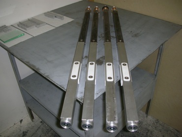
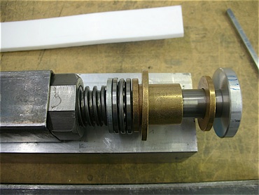
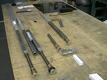
Finish build and assemble the four legs containing the roller chain sprocket, bronze flanged-sleeve bearing, ball bearing, spindle, Acme coupling nut, steel square tube, aluminum square rod, Teflon pads and leveling mount.
The legs go into storage till the next step in developing the Cube Box goes under way.
Roller chain sprocket


Bronze flanged-sleeve bearing

Ball bearing


Leveling mount


Four Teflon pads

Aluminum square rod

Steel square tube

Spindle


Acme coupling nut


July 2008
Turning Point
Albert arrives in New York on July 4th; it is his first Independence Day in the USA!
We try again to find a concept for a lifting mechanism that will work and that we can afford. As we had learned from our experiences in April with the Swiss company specialized in hydraulics, we have to find a simple, mechanical solution.
So we put our brains to work and do sketch after sketch, teasing and laughing about each others brilliant design ideas, but nothing seems to be pointing towards a breakthrough. A few sketches are below without comments.
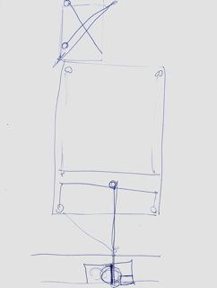
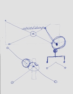
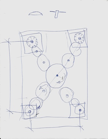
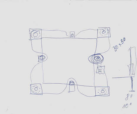
On one point Albert comes up with the sketch to the left, drawn in Plan. He explains that each circle represents a gear, powered by the one in the center and spreading diagonally to the one at each corner of the Cube Box. The gear in each corner attaches to a vertical spindle. The spindle moves up and down in a nut that is attached to the main frame of the Cube Box. Each spindle would be extended to a leg by a square rod and moving inside a square tube that is part of the main frame.
That way, he argues, all four legs move up or down absolutely simultaneous. Although an interesting idea there needs to be a simpler solution for all the gears.
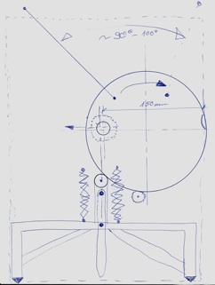
36”

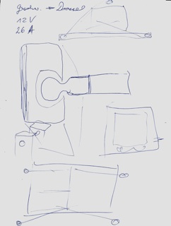
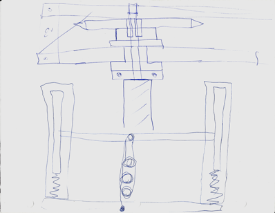
Shortly after, night had fallen already, I once more return from the kitchen with two cups of ice cream when I spot another interesting drawing by my brother. “What’s that” I ask. “Well” he replies “something simple: a bicycle chain that connects a sprocket in each of the four corners. The roller chain sprocket that lies horizontal is attached to a vertical spindle just as we have it with the gear version. An electric motor with the driving roller chain sprocket attached to its shaft drives the bicycle chain. So the gears are basically replaced by the bicycle chain!”
That’s it; simple! And the synchronization of the four legs is always guaranteed. We are all of a sudden back alive, discuss in detail the mechanism and its components and start to piece it together with a source catalogue to get an idea of the costs.
Then some changes occur, another roadblock, a different approach, no matching parts, another idea; nothing unusual. But we stay with the basic concept that fascinates us both: a bicycle chain ...
We finally settle on a doable version and do a rough estimate on it. Even though it is a simple solution the costs of the parts and the materials still add-up to a sizable amount of money. But we decide to go for it and to build a mock-up of the drive mechanism with the four legs as the first step. We order parts for the four sprocket/spindle/leg assembly with the steel tube for the Acme coupling nut. The ball bearings, strips of Teflon and the aluminum we need I have in stock.
While we are building the four legs we realize very quickly that the time left to do a full mock-up until Albert’s departure is not sufficient. We also need to raise more money to buy all the other parts and decide therefore to focus on building the four legs.


Albert leaves New York on July 31st.


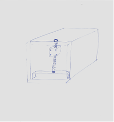
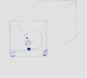
Motor with the driving roller chain sprocket attached to its shaft

Bicycle chain


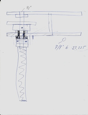
Roller chain sprocket attached to a vertical spindle


Low-profile spring roller chain tensioner

Vertical Spindle

Roller chain sprocket

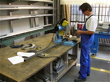
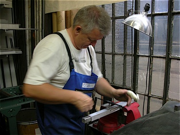
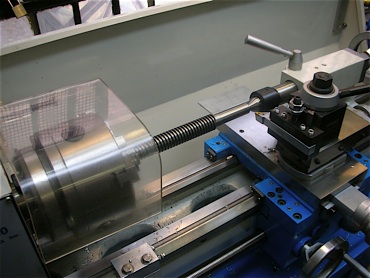
The spindle material is cut to length and shaped on the lathe.
The four steel square tubes are cut to length.
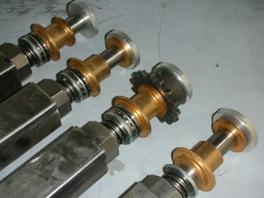
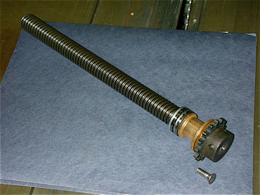
The spindle receives the roller chain sprocket, the bronze flanged-sleeve bearing, a ball bearing and a steel washer.
The coupling nut is milled, fit and welded into the steel square tube.
Each of the four aluminum legs is detailed to fit into its steel square tube and to receive the four Teflon pads.
The four legs in different stages of assembly.
Steel square tube

Square aluminum rod

Four leveling mounts

Coupling nut

Spindle

Roller chain sprocket

Teflon pads

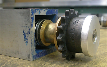
Square aluminum tube of main frame

Spindle assembly with the roller chain sprocket protruding out of the square aluminum tube of the suggested main frame.