Cube Box (2006 - 2010)
Progress December 2009

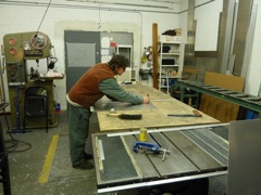
Main Fabrication of The Cube Box
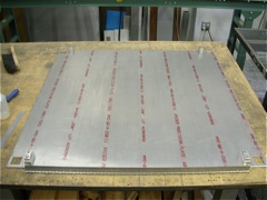
Next is the fabrication of the base plate that includes the attachment of the hinges for the two doors and the posts connecting the base plate to the main frame. The relatively thin 1/4” base plate also receives two sets of angles to reinforce it and to help guide the Cube into the Cube Box as well as holding it securely in place for transportation.
1/4” base plate
1 of 4 posts connecting the base plate to the main frame
Hinge for one of the two doors


Fabrication of the two doors. The doors (1/8” aluminum sheets) also act as ramps to wheel the Cube onto the 1/4” base plate and therefore receive reinforcement angles as well. They also guide the Cube into the box.


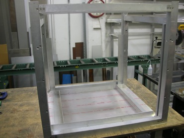
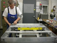
Fitting the base plate to the main frame
2 sets of reinforcement/guide angles are attached to the 1/4” thick base plate


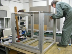
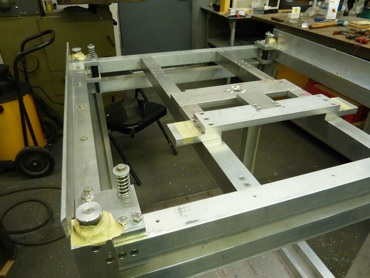
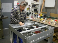
Parts are continuously built and added to the main frame.
The remaining parts for the chain mechanism are being produced and installed into the main frame.
The motor is attached to the main frame.
Fabrication and detailing of the two doors (1/8” aluminum sheets).
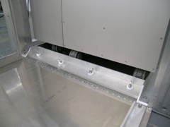
Detail of the hinged door and the reinforcement/guide angles attached to it. The two set of angles on the base plate hold the Cube securely in place for transportation.
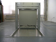
The door is mounted to the base plate and is in open position with the reinforcement/guide angles attached to it. The Cube is wheeled into the box.
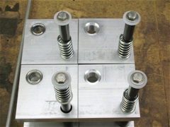
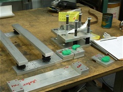
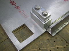
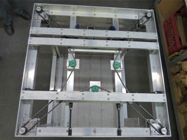
Set of four spring-loaded bolts and its two mounting plates to the main frame. The bolt is held by a sleeve bearing between the two plates.
Parts are built and ready to be added to the main frame.
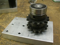
Part of the chain mechanism mounted to its aluminum plate ready to be built into the main frame.
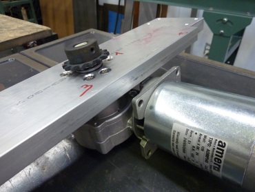
The motor with the driving roller chain sprocket attached to its shaft is mounted to the aluminum plate ready to be built into the main frame.
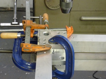
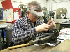
A set of corner plates is clamped into its position for drilling and tapping the holes. The plates will hold a roller chain sprocket and a spring-loaded bolt.
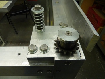


Spring-loaded bolt
Roller chain sprocket
Roller chain sprocket
Spring-loaded bolt


Top frame-angle


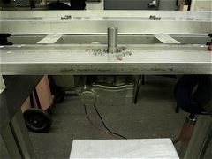

Top guide installed over roller chain sprockets

Motor attachment to the main frame


Roller chain sprockets without top guide


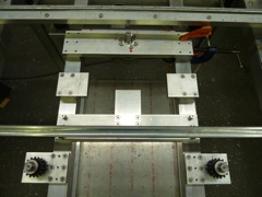
The five chain loops are carefully measured out, assembled and installed by the expert, my brother Albert.
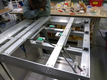
The four chain loops driving the spindle in each leg are powered by the motor driven fifth loop. A last inspection before the test run ...
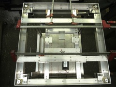
Finally, the mechanism can be tested! Will it work?

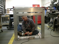
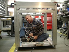
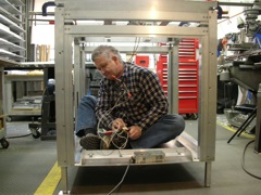
Yes, the mechanism works perfectly, even with Albert sitting on the base plate imitating the weight of the Cube! Click on one of the images to see a video clip. Don’t miss it, it’s really funny!
By looking at the impressive structural composition of the Cube Box and its exposed mechanical components of the chain drive on top of it cause a change of the projected material for the skin of the Cube Box: instead of using wood to clad the aluminum frame, Plexiglas will be used. That way the transparency of the Plexiglas will expose the beauty of the structural framing, the Cube inside of it and the lifting mechanism for the box all at once to the eye of the beholder.
After almost six weeks of intense work with me on the Cube Box my brother Albert returns to Switzerland knowing that our mission to come-up with a working lifting mechanism has been accomplished a hundred percent!
But the work on the Cube Box is not finished yet. What follows next is a modification of the chain mechanism and some framing parts interacting with it.
