


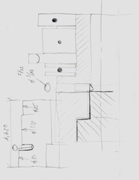
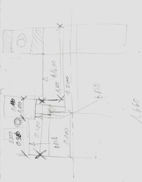
Hinge detail: door attachment to the base plate (Cross Section)

It is one of the most exiting and rewarding stages in the evolvement of a project to see the two-dimensional vision unfold in its three-dimensional reality.
Start cutting the aluminum profiles (tubing) to fabricate the parts for the main frame of the Cube Box.
On November 15th, my brother Albert arrives from Switzerland to engage in the process of fabricating the Cube Box and its lifting mechanism. The first step is going together through the new and revised design details, discuss them and adjust some. Especially the business of the bearings for the shafts that hold the roller chain sprockets in place takes some time. But Albert is the specialist and leads the team effort.

Door, Guide Angles Excerpt
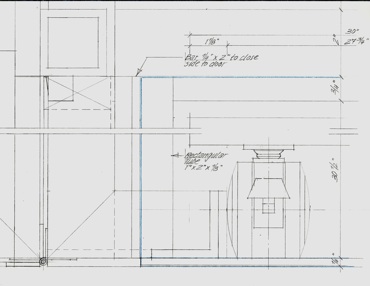
Cross Section/Elevation Detail

Blue line: outlining of the door (Elevation)
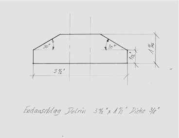
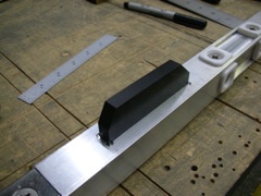
Stopper Bar
Elevation
It also turns out that the legs we fabricated back in January are too long according to the revised main frame design. They are quickly modified.
We decide on the final design for the Stopper Bar and accordingly where the slots go for its up and down movements in the aluminum legs.
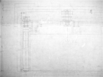
Excerpt of Scale Drawing (at Albert’s arrival)
Cross Section, Detail
Bearing Sketches: Altered Design (by Albert)
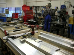
We settle on a few more design details and then the fabrication process of the Cube Box goes into full swing!
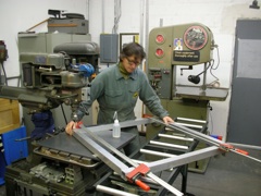
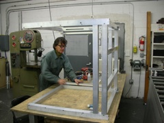
Individual parts are fabricated to specifications and readied to be put together for the main frame.
Stopper Bar on the inner leg part (solid aluminum).
Holes are drilled and tapped to assemble a part of the main frame.


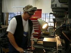
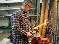
Albert mills the slot for the Stopper Bar into one of the four outer, hollow aluminum legs.
The main frame is finally growing.
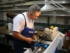
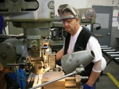
Albert cuts the four steel rods for the spring-loaded bolts.
He then turns the ends plane and to its precise length.
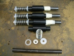
The four spring-loaded bolts with all the parts involved.
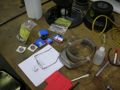
Parts and sketches to build the shafts with the bearings and the roller chain sprockets laid out on the table.
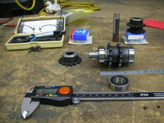
Bearings, roller chain sprockets and shafts next to tools.
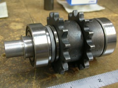
Bearings and two roller chain sprockets assembled on its shaft.
Cube Box (2006 - 2010)
Progress November 2009


Main Fabrication of The Cube Box
Continue work for the scale drawings of the Cube Box. Study the details for the two doors and the slots in the legs for the Stopper Bar that switches the up and down mechanism on and off.