Mock-Up
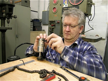
Then it’s time to build the mock-up. The four legs (spindle with roller chain sprocket) and the motor with the driving roller chain sprocket are mounted to a wooden base plate. The motor is hooked-up to a 24-volt transformer.


Cube Box (2006 - 2010)
Progress January 2009 Part II


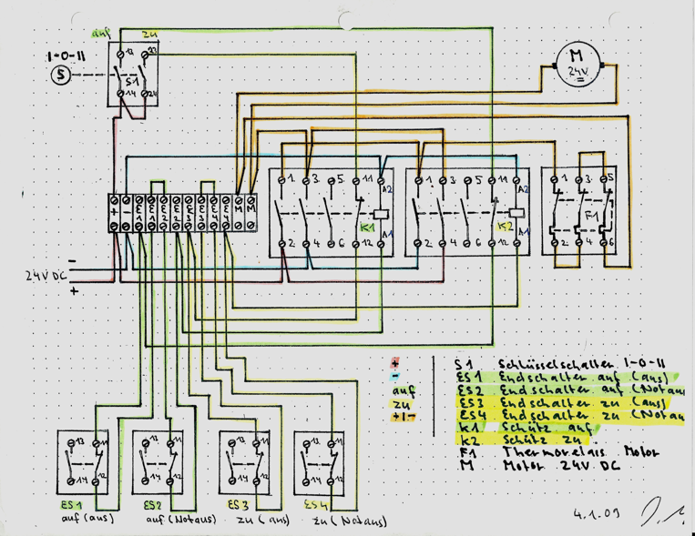
On January 14th the electric components (microswitches, relays, circuit breakers, main switch) for the controls of the linear motion arrive by mail from Switzerland since Albert could not get everything together in time before his departure. It also includes the wiring diagram by Daniel Wyss, Switzerland, who designed the electric controls of the linear motion.
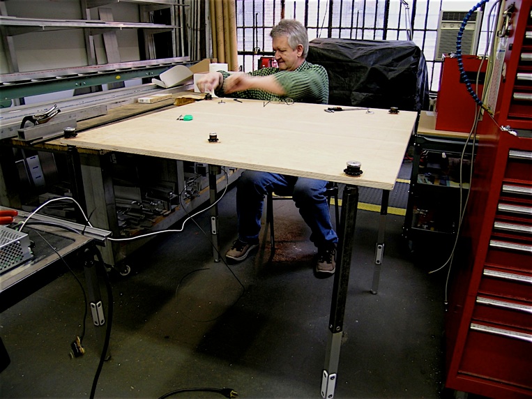
As we try out the mechanism it becomes quickly clear how complex the hole thing is. In order to figure-out the correct power requirements for the motor we need to stabilize the legs to be able to judge the resistance of the spindle in the coupling nut.
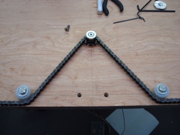
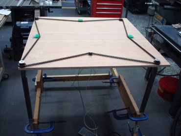
Another issue is the chain drive in conjunction with the driving roller chain sprocket: the projected angle in this Picture is too flat. The chain keeps jumping sprockets.
The version in this picture with a 180° bend and two additional guide rollers is too tight.
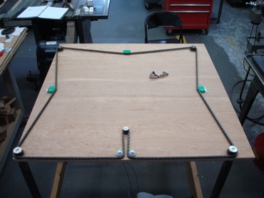
The version in this picture with a 90° bend and two additional guide rollers is better than the previous one but still too tight.
We also build a version where each leg is powered by its own motor without the chain drive. Problem: how to synchronize the four motors.
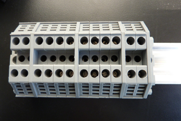
Terminal blocks mounted onto DIN-35 rail.
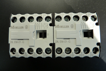
One DC contactor open, one DC contactor close.

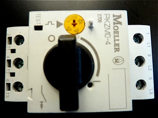
Motor protection switch.
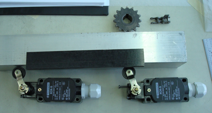
Micro limit switches, Delrin block to build stopper bar.
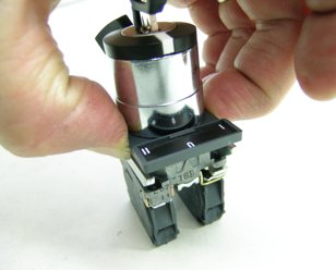
Key switch (main switch).
Electric controls of the linear motion and its wiring diagram by Daniel Wyss, Switzerland.

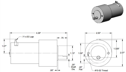
Schematics of the miniature DC gear-motor, 24 Volts (drawing by McMaster-Carr Supply Company).


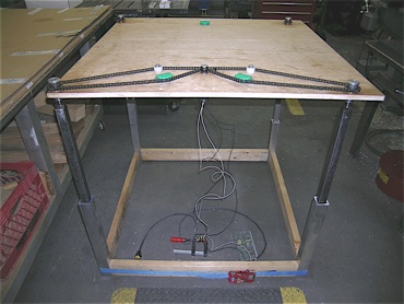
After stabilizing the legs and trying out another version of the chain drive with two loops and motors (see picture A) we realize three things:
-
1)we want one motor
-
2)the chain drive has to be as short as possible
-
3)we need a stable frame between the legs (vertical) and the chain drive (horizontal) to be able to judge if the power of the motor is strong enough.
Conclusion
We come up with an idea for the chain drive that has four chain loops (one for each leg) on one level and the driving chain loop that connects the four chains on another level. That way, we believe, the driving chain will be short enough to handle the job without the danger of skipping sprockets on the driving roller chain sprocket.
We decide to go ahead to design and build the aluminum frame for the Cube Box. Since we are running out of time, the building of the frame has to be postponed to another time slot when we can work together.
We also research another, stronger motor that runs on 24 Volts and is compact. We find something interesting on the Internet and get in touch with the company in Italy, Amer SPA. After an initial direct Email exchange with the Italians I get referred to its American representative, Amer Electric Motion.
After three exciting weeks working together Albert returns to Switzerland.
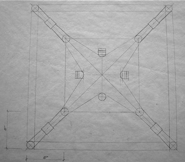
I start doing the scale drawing (see picture B) of the revised chain drive for the lifting mechanism.
A
B
Miniature DC gear-motor, 24 Volts